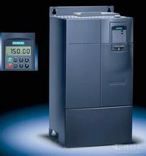
1. It is necessary to pay special attention to the analog input (voltage or current signal). It is not enough to modify the P756. The DIP switch on the terminal board must be set to the correct position. See upload picture - inverter analog input
DIP1 (left) analog input 1 is set to OFF to indicate 0-10V and analog input 1 is set to ON to indicate 0-20mA.
DIP2 (right) analog input 2 and DIP1 are the same.
2. Please set according to the picture content, then observe the operation status of the frequency inverter, and the frequency display is normal.
If there is an abnormality, you use a multimeter to measure in series, and the mA value of the current can be used to determine the cause of the problem by observing the values of parameters r0752 and r0754. R0752 (analog input actual value) and the actual voltage value is the same (with multimeter terminal).
The value of r0752 is monitored, which is the value of the actual input current or voltage. R0752.0 is the analog input 1, r0752.1 is the analog input 2, which is a most direct, most convenient and most effective way.
To eliminate the possibility of analog signals being disturbed, consider increasing the P0753 filter time.
Siemens inverter repair
Siemens inverter repair center
SIEMENS/Siemens Inverter Repair Center/Maintenance Service: 24H Service Hotline: 15800462088
Siemens inverter repair center, provide home maintenance inspection and repair services: 24H service hotline: 15800462088

